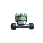
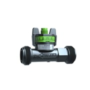
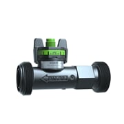
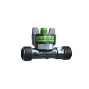
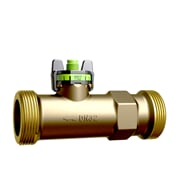
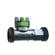
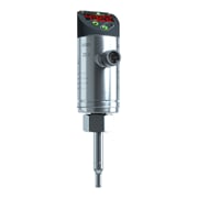
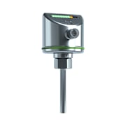
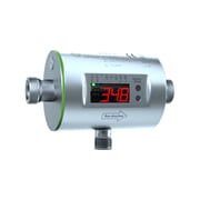
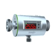
Flow meters
Flow meters monitor the flow velocity or flow rate of gaseous or liquid media. Measurements are reliable and wear-free and also include temperature values. Deviations from individual threshold values that could lead to impaired quality, damage or downtime are detected at early stage, allowing preventive measures to be adopted. Read more here
 Cloud compatible
 20 in stock!
Online -5,5 %
269.93 €
255.08 €
The right flow velocity sensor for each application
In this section you'll find all relevant information about flow sensors in one place including step-by-step instructions guiding you through the selection of an appropriate flow sensor for your application and an overview table with all autosen flow sensors. It helps you find the appropriate device for your application quickly.
What is a flow sensor?
Flow sensors monitor the flow velocity or flow rate of gaseous or liquid media thus ensuring optimum operational sequences. The measurements are reliable and wear-free and include additional data such as temperature values. Deviations from individual threshold values that could lead to impaired quality, damage or downtimes can be detected at an early stage, allowing preventive measures to be adopted.Due to the various types of construction and measuring processes, the autosen flow sensors can be used for a broad range of applications in process technology, process engineering and plant engineering. Electronic flow sensors cover a broad spectrum of applications ranging from simple limit value monitoring to the exact determination of flow rates. Harmonised operating menus make it easy for users to adjust settings – even where different flow sensors are involved. With analogue, binary and pulse outputs, users can choose between many options regarding further processing of the measured data. Our flow sensors are available as flow sensors and flow meters.
Properties of flow sensors
Flow sensors have no movable parts and are therefore insensitive to dirt and operate wear-free. The autosen flow sensors are based on three different measuring principles: Calorimetric (AS001/AS005), electromagnetic (AS002-AS004) and vortex (AS006-AS010).How does a flow sensor work?
The different types of flow sensors and their functional principles and measuring principles are explained in section "Types of flow sensors and measuring principles".Selection of appropriate flow sensor in 9 steps
The selection of the flow sensor depends on the requirements of the application. We summarised step-by-step instructions with the most important criteria and listed all flow sensors in a practical table to facilitate your selection and to help you quickly determine the appropriate device for your application.- Do you intend to measure a liquid or gaseous medium?
- Which medium?
- Flow measuring range
- Temperature measurement range
- Pressure range
- External influences (air bubbles, rapid temperature changes, viscosity changes)
- Inline or immersion sensor and pipe size
- With a display or without?
- Local reading or remote monitoring
Step 1: Liquid or gaseous?
Only flow sensors AS001 and AS005 are appropriate for measuring gaseous media. They can also be used for liquids. The other flow velocity and flow rate sensors can only be used with liquids.Step 2: Which medium?
The medium in which the sensor is intended to take measurements has to be reviewed to select the appropriate flow sensor. Please find an initial overview of our flow velocity sensors and flow rate meters in this table.Step 3: Flow velocity / flow rate measurement range
Step 4: Temperature measurement range
Step 5: Pressure range
Step 6: Other external influences
Step 7: Inline or immersion sensor and pipe size
Inline flow velocity sensors form their own measuring tube. This brings the following advantages:- Installation is facilitated versus immersion flow velocity sensors
- Less restrictions when installing the sensor (see section about installation conditions)
AS001 and AS005 are immersion flow velocity sensors. AS002-AS004 and AS006-AS010 are inline flow meters. The pipe size has to be considered for inline sensors. Immersion sensors are laterally installed in a pipe. This brings the advantage that the same sensor can be mounted in pipes of different diameters. This offers more flexibility for installation. At the same time a greater number of installation conditions have to be observed.
Step 8: With a display or without?
Step 9: Local reading or remote monitoring
Local reading is possible quickly and easily on the display. If it is intended to monitor the measured values of the sensor from remote, you can easily use our IoT gateway io-key IO001. Every IO-Link-capable sensor can be just connected to the gateway and the measured values are immediately radio-transmitted via NB-IoT into the cloud and displayed on an individual dashboard. You can also set up alarm messages which are directly sent to your mobile phone as an SMS so that you are always up-to-date and able to intervene rapidly if problems occur. Appropriate sensors in connection with the io-key: AS002-AS005.Calorimetric flow velocity sensors
Calorimetric flow velocity sensor / thermal flow velocity sensor Calorimetric flowmeters, also referred to as thermal flowmeters are electronic flowmeters operating according to the thermal principle. The sensor tip is directly placed in the pipe with contact with the medium. Inside the probe there are two temperature sensors. One sensor is heated, the other one used as reference. If the medium to be measured flows through the pipe, the heat is removed from the heated temperature sensor and the temperature difference changes as a function of the flow velocity. If the medium is at standstill, the temperature difference between the heated sensor and the reference is equal to zero.Calorimetric flow velocity sensors are used for the following:
- Liquid and gaseous media (ultrapure, without particles and solids)
- Monitoring of agitators, cooling circuits, etc.
- As dry pump protection
- Flow monitoring in pipes
Sensors AS001 and AS005 from autosen are calorimetric flow velocity sensors.
Vortex flow meter (VDM)
Vortex flowmeters are based on the principle of the Kármán vortex street. In a pipe with media flowing through and/or in a special measuring tube a baffler is mounted behind which the flowing medium produces a vortex and this is referred to as vortex street. The inverse vortexes produce local pressure differences measured by a piezo element. The sensor calculates the flow velocity on the basis of the occurring pressure pulses per time unit. Vortex flowmeters are used for water, water-glycol mixtures and coolants.The autosen sensors AS006-AS010 are vortex sensor.
Electromagnetic flow rate sensor (MID)
The functional principle of electromagnetic flow rate sensors is based on Faraday's law of induction. They are made up of a metal measuring tube with an inside electrically isolating coating and two measuring electrodes arranged transverse to the magnetic field. To be able to measure the flow velocity with an electromagnetic flowmeter, the medium to be measured has to have the minimum conductivity of 20 microS/cm. The conductive medium flows through the measuring tube, and thus through the magnetic field at a right angle. The measuring electrodes arranged transverse to the magnetic field detect the voltage generated by induction. Faraday's law of induction sais that if a conductor is moved through a magnetic field at a right angle, the voltage produced in the conductor is proportionately to the velocity of the conductor. This is how the flowmeter calculates the flow velocity of the medium. The measuring principle is independent of the medium temperature, pressure fluctuations and the medium composition. Only the following basic prerequisites have to be complied with: Conductive liquid media (conductivity: >= 20 µS/cm / viscosity: 70 mm²/s at 40 °C)To be labelled only: Magnetic field, measuring electrodes, flow velocity
Electromagnetic flowmeters are optimally suited for
- Water
- Waste water
- Other conductive or contaminated media
- Applications with a small pressure drop only and low maintenance expenditure
The MID flowmeters are not suitable for:
- Oil
- Hydrocarbons
- Many non-water-based solutions
- Deionised water
The sensors AS002, AS003 and AS004 are electromagnetic flowmeters.
Typical applications of flow sensors
Flow sensors can be used amongst others for the following tasks:- Monitoring of coolant/lubricant supply of machines
- Spray jet monitoring in cleaning systems
- Monitoring of units
- Dry pump protection of pumps in compressors and heat exchangers
Installation conditions for flow velocity and flow rate sensors
Bends, valves and internals in pipes and reducers, etc. cause turbulences of the medium and may impair functioning of the device. Some factors have to be observed for installation to ensure proper operability of the sensor. The basic rules for installation of the sensors are summed up in this section. You will find more detailed information and the device-specific conditions in the operating instructions of your sensor and also download this information on the item page of the device.Installation conditions for immersion flow velocity sensors
- The sensor tip has to be completely surrounded by the medium and must not contact the pipe wall.
- No installation in downpipes open to the bottom
It is also recommended:
- Installation should be lateral for horizontally routed pipes
- Installation in the riser for vertically routed pipes
possible:
- If the pipeline is free from deposits, the sensor can be installed from below for a horizontal pipe
- If the pipeline is completely filled with the medium, the sensor can be installed from above for a horizontal pipe
Installation conditions for inline flow velocity sensors
- Install the device such that the measuring tube is always completely filled
- Provide an inlet and discharge section
Not recommended:
- Installation directly behind shut-off/control devices
- At the suction side of a pump
- At the highest point of the piping system
- In an open downpipe
It is also recommended:
- Install in front of or in a rising pipe


